D8224 Sound Board
This information applies to the Williams D8224 Sound board. The D8224 is a simple, single-board computer with a Central Processing Unit [(CPU) either a 6808 or 6802], Random Access Memory (RAM), code [Read Only Memory (ROM)], and controller [6812 Peripheral Interface Adapter (PIA)] chip that executes sounds for many Williams video games and pinball machines. This specific board was designed to run such Williams video games as Defender, Stargate, Robotron, Joust, Splat!, Sinistar, and Blaster. As mention, Williams also used it as a sound board for many of their pinball machines. This board can be identified by the serial number IC-2001-146-X, where the X denotes the revision number of the board. This serial number is etched on the PCB. Click on the image below for a high-resolution image of the D8224 Sound board.

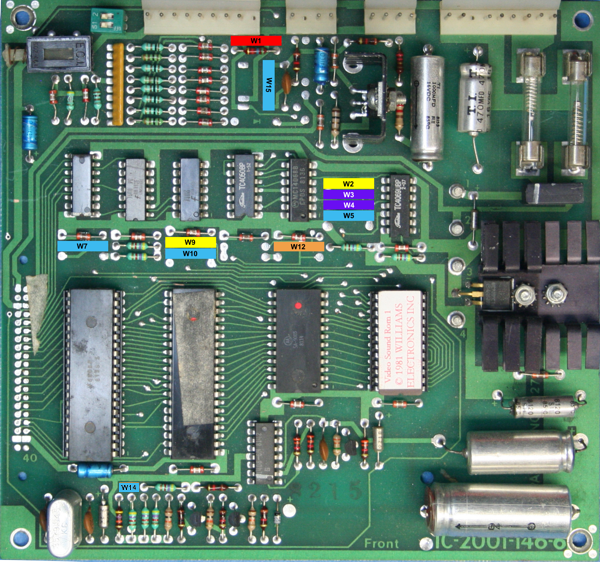
Figure 1 - The D8224 Sound board with jumpers W1 through W15
Figure 1 jumper color legend
RED jumpers are for games that do not require an additional C8228 Speech Board
YELLOW jumpers are for games that run 2516 or 2716 EPROMs as IC12
PURPLE jumpers are for games that run 2532 EPROMs as IC12
BLUE jumpers are for all games
ORANGE jumper specific to Blaster only
The D8224 Sound board can be configured to run Defender, Stargate, Robotron, Joust, Splat!, Sinistar, and Blaster. Depending on what game you want the sound board to run, depends on three things; 1) the type of EPROM you want to install in IC12, 2) the EPROM file loaded onto the EPROM, and 3) the configuration of the jumpers. In addition, this board is capable of running Sinistar, but requires the use of an additional C8228 speech board.
A "jumper" is simply a 0 Ohm, 1/4 watt resistor. There are fifteen jumper locations on the D8224 Sound Board. Refer to Figure 1 for each jumper location and Table 1 for what games use what jumpers and specific PROMs/EPROMs. I'm not going to cover the plethora of pinball configurations this sound board can be used for, I'll stick to Williams video games only.
| Jumpers Used | EPROM Type | Format | Games Used In | EPROM Filename |
|---|---|---|---|---|
| W1, W2, W5, W7, W9, W10, W15 | 2516 2716 |
Sound Only | Defender Stargate |
Video Sound ROM 1 Video Sound ROM 2 |
| W1, W3, W4, W5, W7, W10, W15 | 2532 | Sound Only | Robotron Joust Bubbles Splat! Sinistar (Cockpit Rear) |
Video Sound ROM 3 Video Sound ROM 4 Video Sound ROM 5 Video Sound ROM 8 Video Sound ROM 10 |
| W1, W3, W4, W5, W7, W10, W12, W15 | 2532 | Sound Only | Blaster | Video Sound ROM ? |
| W3, W4, W5, W7, W10, W15 | 2532 | Sound & Speech | Sinistar (Upright & Cockpit Front) |
Video Sound ROM 9 |
Table 1 - The D8224 Sound board with jumpers explained.
D8224 Sound Board - CPU/Memory Configuration (W14 Jumper)
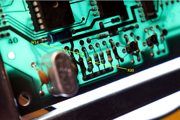
The D8224 sound board has a CPU located at IC9. This can either be a Motorola 6802 or Motorola 6808, both are pin compatible. However, the 6802 CPU differs in that it has 128 x 8-bit on-chip RAM (128 bytes) but is not enabled by default. Williams engineers soon realized the RAM on the 6802 often became unreliable and in addition, these chips were more expensive to manufacture than their 6808 cousins. By default, pin 36 (RE - RAM Enable) of the 6802/6808 is tied to ground (TTL low), which enables the CPU to use the on-board memory chip (Motorola 6810) at IC11. This is accomplished with a foil/trace jumper (W14) underneath the 4.7kOhm resistor at R30 (see Figure 2). In order to enable the on-chip RAM of the 6802, cut the foil/trace jumper under R30, which will pull the signal to TTL high. The Motorola 6808 relies soley on the 6810 RAM located at IC11, while the 6802 can use either the 6810 or its own on-chip RAM depending on the W14 jumper configuration. If a Motorola 6808 CPU is used, the W14 jumper (foil/trace) must be intact.

Figure 2 - The D8224 Sound Board W14 jumper location
| CPU Used | RE (RAM Enabled) | IC11 RAM Used? |
|---|---|---|
| Motorola 6808 | No (W14 Intact) | Yes - Motorola 6810 needs to be installed |
| Motorola 6802 | No (W14 Intact) | Yes - Motorola 6810 needs to be installed |
| Motorola 6802 | Yes (W14 cut) | No - Motorola 6810 should be removed |
Table 2 - The D8224 Sound Board CPU/Memory configuration.
D8224 Sound Board - General Troubleshooting & Repair
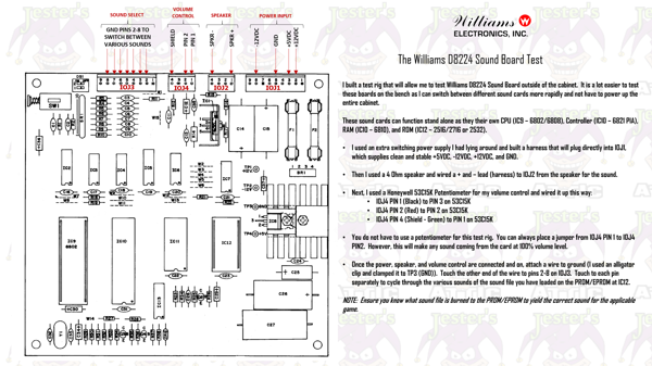
The most effective way to test the D8224 sound card is to build a bench-top test rig and test the board on the work bench. This will allow you easier access to components when probing with a DMM. Refer to the instructions below to understand how to build the sound board test rig.

Figure 3 - The D8224 Sound Test Rig
The first thing I like to do before trying to troubleshoot any issues with the D8224 Sound Card is replace all the electrolytic capacitors. Some of these boards are over forty years old. If the caps are original, chances are they are dried up, out of tolerance, and/or not serviceable. Why risk it? Do yourself a favor and replace all the capacitors with good qualilty capacitors like Nichicon or Panasonic. It will help save you from having issues later. I get sound boards all the time that are just hacked to death. I've seen people take a bridge rectifier and lift it two inches off the board. It's common to see radial capacitors installed where an axial capacitor should be (and vice versa). I've seen straight wires in place of jumpers on these sound boards and ICs soldered on top of other ICs. The last board I rebuilt, I completely removed every component from the board and installed everything brand new back on to it. I know that board will give me no trouble for years to come. I will assume that you have already installed a complete cap kit on the board you are working on. Here are some basic troubleshooting tips:
Check the fuses (F1 & F2) - The easiest thing to troubleshoot is checking the fuses at F1 and F2. Both of these are 4 Amp, slow blow fuses.
Check the connectors - The next thing you should do is to replace all the header connectors at IOJ1, IOJ2, IOJ3, and IOJ4. I can't tell you how many times I've been burned by a bad connection. It's best to elimnate any possiblity of a bad connection from the start. Yes I know, it's tedious. But it will save you a ton of headaches in the future. At a minimum, at least resolder all the connectors.
Check the audio amplifier (IC1) - If you are getting zero sound from the board, chances are the TDA-2002 Audio Amplifier at IC1 is bad. Turn the power on to the board, turn the volume way up, then rub your finger over the leads of the audio amp. If you hear a humming sound coming from the speaker when you touch the leads, chances are the TDA-2002 is good. If you don't hear anything, swap the audio amp out with a new one.
Check the test points (TP1 through TP4) - Ensure you are getting the correct voltages for each. If not, check the power connector and ensure you are getting the correct voltage at the connector. If you are not getting 5V, check the output of the 7805 at IC8.
Press the reset switch (SW1) - If you press the reset switch and you hear some game sounds coming through the speaker, you know the following components are working:
- IC9 - 6808/6802 CPU
- IC10 - 6821 PIA
- IC11 - 6811
- IC12 - 2516/2716/2532
Note: It is normal for the sound card to play the same sound over and over after pressing the reset switch.Check the CPU (IC9) - Check the data (pins 26-33) and address (pins 9-20 & 22-25) lines on the 6808 CPU. If any of these are dead, replace the CPU.
Check the PIA (IC10) - If you still don't hear any game sounds coming through the speaker, chances are the 6821 Peripheral Interface Adapter (PIA) IC is bad. These are notorious for going bad. One of the first things I check on a sound board is the 6821. If the chip is socketed, pull the IC out of the socket and ensure none of the legs are broken. Unless the chip looks new, clean all the legs carefully and re-insert the chip back in the socket firmly, ensuring each leg is fully inserted (eg. not bent, broken, missing, etc.). If you still don't get any game sounds, swap out the 6821 with a known working chip. If no socket is installed, install a 40-pin socket on the board. This will save you time in the future if the PIA goes out again.
Check the buffer (IC5) - If you still do not hear any sounds, check/replace the 4050 buffer at IC5. I've never seen one of these ICs socketed from the factory, so if you are going to replace it, put in a fresh socket.
Check the ROM (IC12) - I like to ensure that the 2516, 2716, or 2532 (depending on the game) at IC12 has the correct sound file burned to it and that the chip is in good working condition. It's easier to get your hands on a 2532 chip than the 2516 or 2716. But if you are working on a Defender/Stargate, you may not have a choice.
Check the RAM (IC11) - Next check the 6810 RAM chip at IC11. It's highly doubtful that this chip is socketed, but you know the drill by now, go ahead and socket it. If you do not have the datasheet for the component you are working on, get the datasheet. There is no way you will be able to confirm if the component is within specifications if you have nothing to compare it to.
If you do all of the above and you're still not getting any sound, it's time to get out the schematics, Digital Multi Meter (DMM), and/or Logic Probe and start checking traces, other Integrated Circuits (IC), and transistors on the board. In addition, thoroughly inspect the board for damage (burned areas, nicks, physical damage, etc.).
