It’s no big secret, my favorite video games are those made by Williams Electronics, Inc, who produced arcade video games from the late 1960’s until the mid 1980’s. In my opinion, they really hit their stride in the early 1980s with titles like Robotron: 2084, Joust, Defender, Stargate, and Sinistar. I can’t tell you how many of these games I’ve owned and sold over the years. Well I’ve recently told myself that when another one of these games come around, I’m going to buy it and keep it. That’s just what happened with my recent purchase of a Williams Defender.
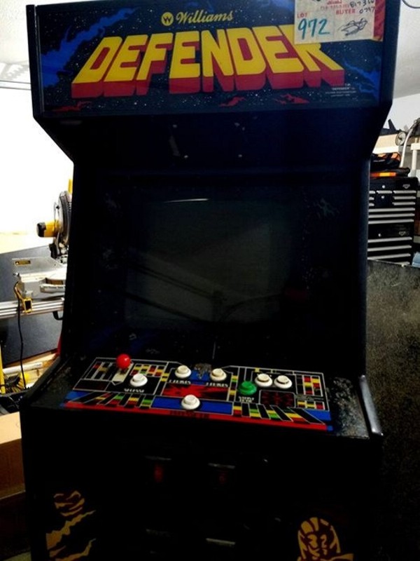
Looks like the guy that had it before me let it sit in the garage for quite a few years in a state of disarray. I guess he got sick of looking at it and posted it on Craigslist. I was fortunate enough to be able to pick it up for $140…complete (not working). I’d rather purchase a complete non-working game than any other because they are less expensive and to tell you the truth, they’re not that hard to get functional again with a little time and patience. As an added bonus, when I picked this one up, there was a Black Widow spider living in the bottom of it. Yikes! I hate spiders.
The guy told me it didn’t have an interface board in it and that was the only thing. Uh huh…right. I get it home to the garage and give it a once over and here are the blatant things I’ve noticed with it:
- Power supply is not functioning
- It’s got a Robotron/Joust interface board in it
- There is no bulb in the fluorescent marquee fixture
- There are TWO wiring harnesses in it…I’m still laughing
- Plenty of cigarette burns on the control panel
- The Wells Gardner K4600 desperately needs a cap kit and some attention
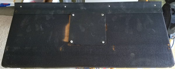
- The original speaker grill is broken – somebody screwed a completely different grill to the original
- The original speaker was replaced by one that is way too small
- The top marquee bracket is not original and doesn’t cover the entire marquee
- Coin door is missing the lock
- No coin bucket
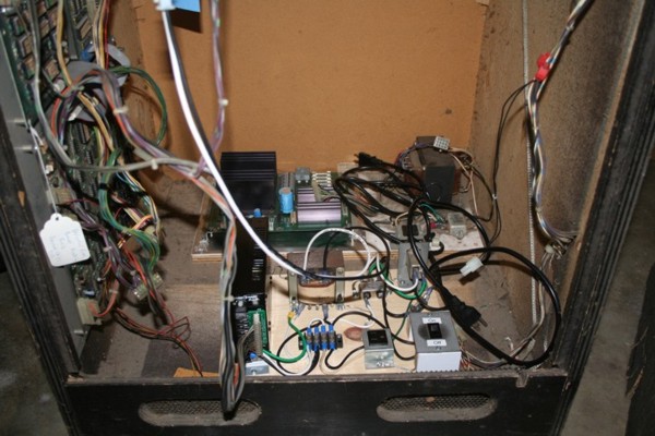
I put another working power supply in the bottom for a quick power on test – no dice.
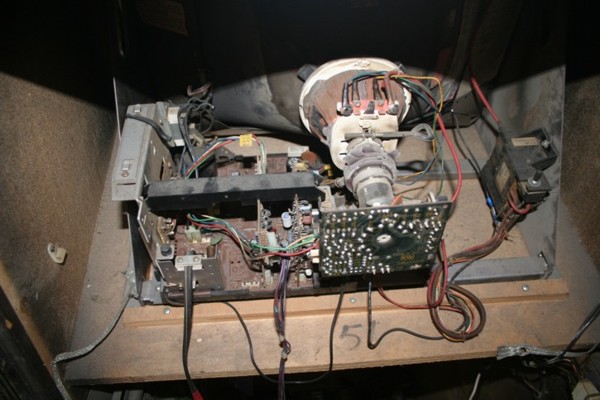
The K4600 monitor definitely needs some TLC.
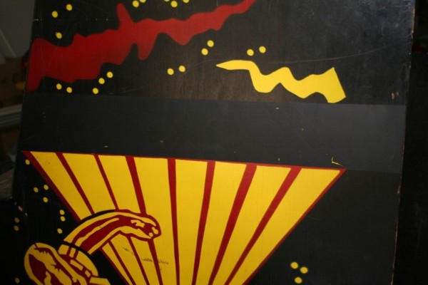
Some jackwagon painted over the “Defender” logo on the side art.
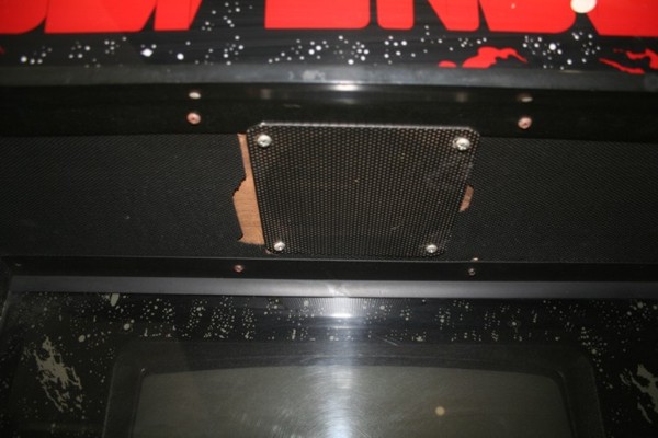
Nice speaker grill.
The control panel looks like someone used it for an ashtray.
I’ve started at the top and will work my way down. First thing is I need to get that monitor right. I ordered all the parts for a cap kit (and then some). I can start working on that and get it tested in some other games I’ve got working. I need to get the correct interface board and I’ve got some feelers out on a replacement. I’ll update this page with the results as I progress through this adventure.
I got around to pulling the 19" Wells Gardner K4600 monitor out of the Defender today.
I had ordered a new cap kit this past week and it came yesterday. I might as well get started giving this tired monitor a new outlook on life.
If you've never worked on a Wells Gardner K4600, it probably shouldn't be the first monitor you put a cap kit in. These things, although beautiful when
done right, can be a giant pain to work on. Adam Hill put together a really nice
video and tear down guide for all of you first-timers.
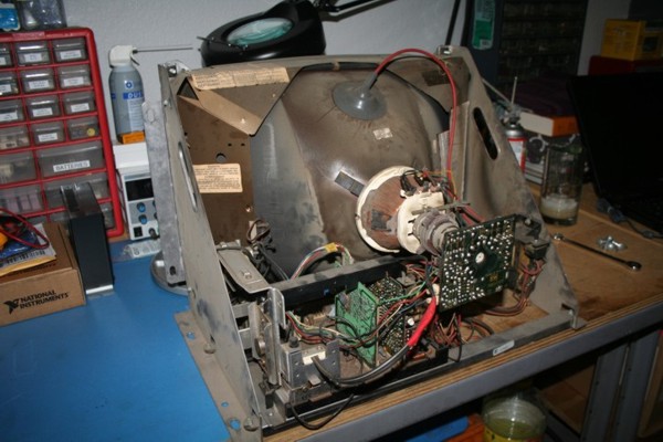
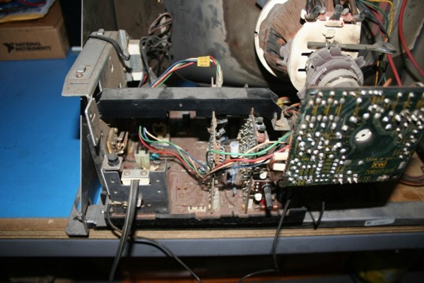
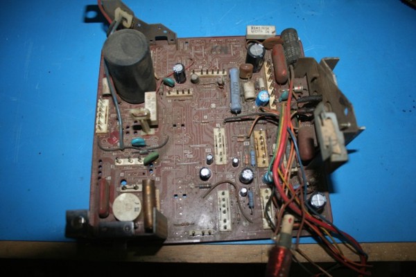
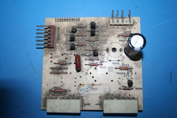
After a much closer inspection, somebody went in front of me and really fubar'd up a previous cap kit. In the last two weeks, this is what I've corrected:
- Replaced C201 on the Interface board
- Replaced C306, C310, C311, C313, C315, C356, C359, and C362 on the X/Y board
- Replaced C501, C503, and C551 on the Power board
- Replaced C605, C607, C608, C613, C614, C617, C619, C621, C622, C623, C624, C625, C632, and C633 on the Main board
I created a set of cap kit instructions for a K4600. Click here for a PDF version of them. In addition I have created four projects on Mouser (one for each board) that will allow you to order the exact capacitors you need. Click on any of the below links to access these projects.
| K4600 Main PCB |
| K4600 X/Y PCB |
| K4600 Power PCB |
| K4600 Interface PCB |
NOTE: The links in the table above have a quantity of 10 for each capacitor in the list. I always place a minimum order of 10 (or more) for each capacitor that I buy. I do this because 1) I hate order one of anything, and 2) you get a price break at quantity of 10. It should also be noted that I am VERY particular about which brand of capacitors I use. I use Nichicon exclusively for all my cap kits. I've found their quality to be outstanding and the ones I use are generally rated to +105C (or higher).
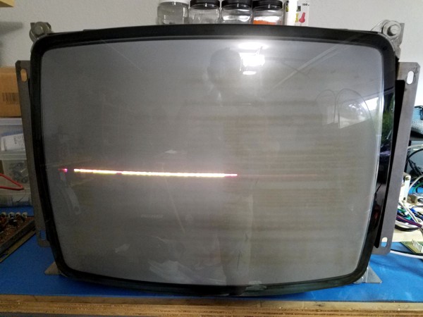
After replacing all those caps (26 total), this is the picture I was rewarded with...vertical collapse/vertical deflection issue.
Studying the schematic, I focused in on the vertical pre-drive, vertical drive, and vertical out sections. I read on the KLOV forum where Ken Layton suggested to change out the resistor at R419 on the Neck board under VR406 because they are known to go bad. So I did. I also:
- Replaced resistors at R314, R315, R316, R317, and R320 on the X/Y board
- Replaced transistors at TR301, TR302, TR303, TR304, TR305, TR306, TR307, TR308, TR353, and TR354 on the X/Y board
I'm definitely making some progress, but I'm not out of the woods yet.
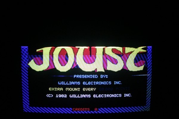
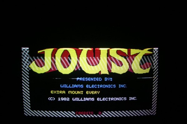
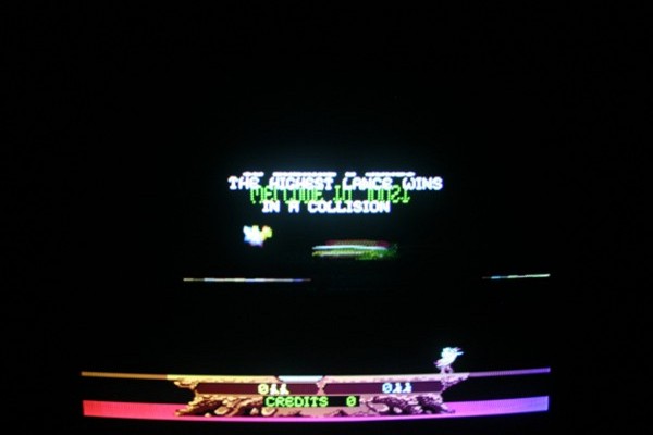
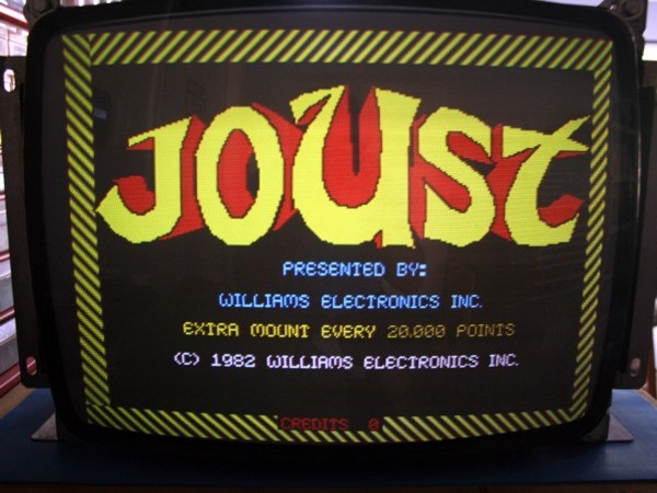
I used a known working boardset to test this monitor with. Joust was the first one I picked. You can see where the top of the screen is folded over while the bottom of the screen is okay. I'm ignoring the discoloration issues in the bottom right corner for now. I know this monitor needs to be degaussed, but I think most of that discoloration is from the orientation of the monitor on the workbench.
For those of you that are interested, these are the transistors I used since the original ones are obsolete:
| Original | Replacement |
|---|---|
| TR301 - 2SA826Q | Toshiba 2SA1015 |
| TR302 - 2SC1740Q | Toshiba 2SC1815 |
| TR303 - 2SC1740Q | Toshiba 2SC1815 |
| TR304 - 2SC1740Q | Toshiba 2SC1815 |
| TR305 - 2SA490YLBGLI | TIP30C |
| TR306 - 2SC1625YLBGLI | TIP31C |
| TR307 - 2SC1740R | Toshiba 2SC1815 |
| TR308 - 2SC1740Q | Toshiba 2SC1815 |
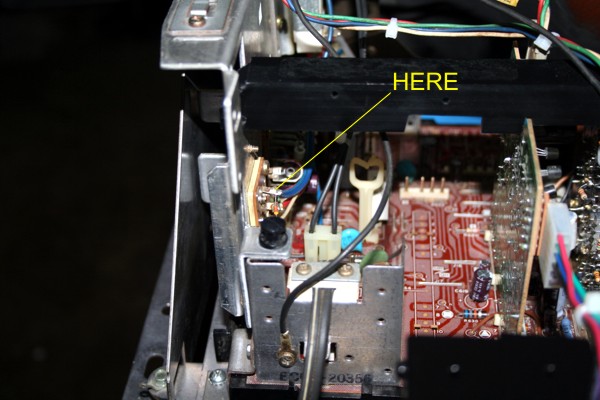
I checked the B+ voltage today and it was a little low at 123.5VDC. I adjusted it up to 127.7VDC. Here's how to check it.
Click on the picture above to get a zoomed in view.
- Turn the monitor on and let it warm up a little to get a more accurate reading.
- Ground the black lead of your digital multi-meter (DMM) to the monitor chassis somewhere, it doesn't really matter as long as you have a good connection.
- There is a blue wire going to TR502 (end of the yellow line in the above picture). Set your DMM to DC. Place the red lead of the DMM to the solder at the end of the blue wire.
- Take a reading. It should read close to +127VDC. If it is too high or too low, adjust the voltage with the potentiometer at VR501. Be careful and don't do like I did to my monitor and pop the plastic adjustment off (like in the above picture).
After adjusting mine from 123.5VDC to 127.7VDC, it still did not fix my vertical issue but now I know I have a good B+ voltage.
It looks like I have resolved the monitor curl issue on the WG K4600. I purchased a few complete K4600 chassis and took one of those XY cards and basically rebuilt it with new components. I did the exact same thing to this newer XY board as I did the original K4600 XY board that has been giving me fits. Once I got all the caps and transistors replaced on the new XY card, the monitor rewarded me with no screen curl or fold over.
BAM! Now after a few quick adjustments, this baby is ready to go back in the Defender. Time to start looking at the Defender board set.
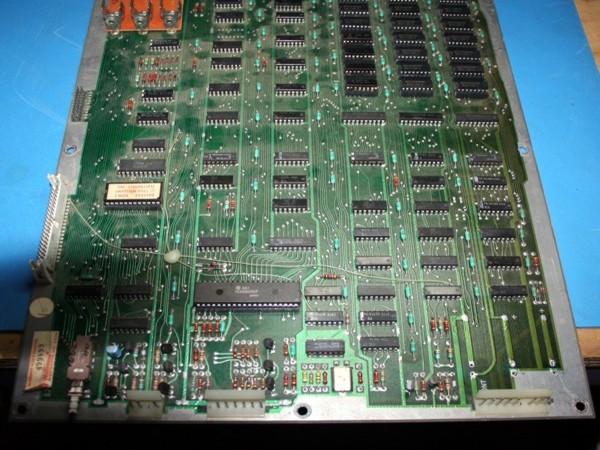
There is no better place to start than the CPU board. If this one isn't right, all the other boards in this set do not matter.
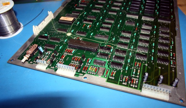
I apologize for the image, my finger must have gotten in the way. As you can see this board is definitely dirty. Anytime I work on a Williams CPU board, I do the following without question:
- Replace the 4116 RAM chips
- Replace the connectors
- Replace the MC6809EP (MPU)
- Replace all the electrolytic capacitors
- Replace all the transistors
- Remove the AA battery holder and replace with a lithium battery holder
- Replace any broken/bad resistors or axial capacitors
I first take a very good survey of the board and check for any broken leads, resistors, capacitors, damage to any traces, and anything glaringly obvious. After a good inspection of this CPU board, it's not in that bad of shape. Pretty dirty, as most boards of this age are, but I've seen much worse. One good thing right off the bat is that there is no battery acid damage as is common for these older Williams boards.
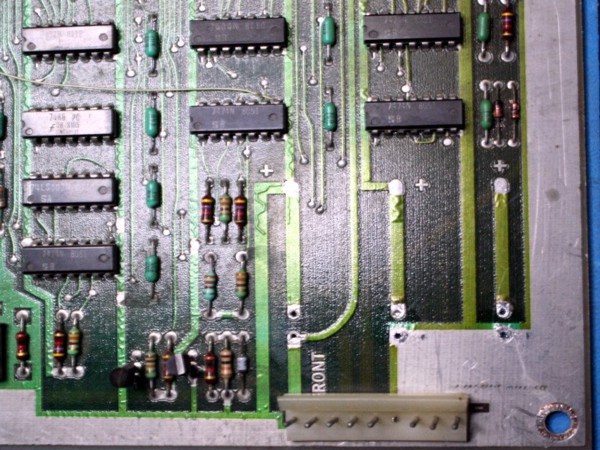
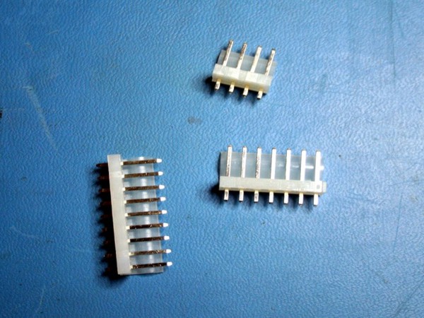
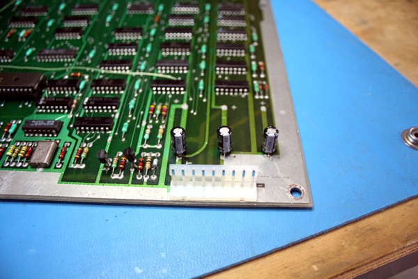
A couple of things to take away from the above picture. These connectors are basically crap. They have round pins and do not always make good contact with the Molex connector. You can also see where this board has been getting hotter on the right side of the PCB than the left. You'll notice the right side of this PCB is less green and more dirty yellow than the left side. That's because that part of the board lives closer to the power supply in the bottom of the cabinet. The heat and Power Supply Unit (PSU) have helped "cook" this PCB over the last 35+ years. I've also removed the three 100uF 25V capacitors from this board in this pic. They will be replaced.
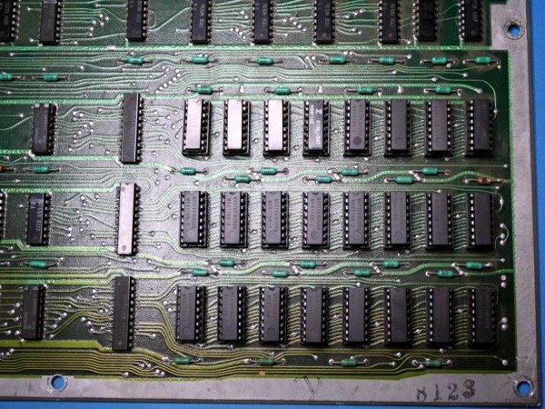
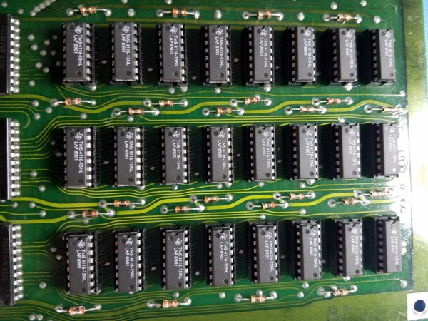
There were two different kinds of RAM in this board, 8116 and some 4116. Who knows what state its in. I always just replace the RAM with new chips so I won't have to worry about RAM issues in the future. You can still buy new 4116 chips for under a buck each at various places on the Internet.
I like these new connectors because the pins are square. It makes for a good contact with the mating Molex connector. You can get these at Great Plains Electronics or Mouser.
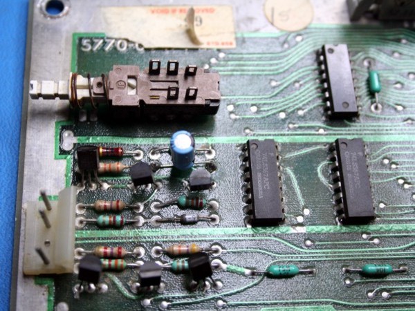
Somebody was obviously in a hurry and used a radial capacitor (blue cap above) where the schematic called for an axial one. That needs to be replaced.
The last OP that had this board had done some sloppy work on the connectors. It looks like these are not original. So I'll need to clean this mess up when I replace the connectors.
Here's the board all cleaned up with the new connectors on it. I like to use a soft bristle brush and some Dawn dish washing detergent and scrub these boards down before I do any work on them. Who wants to work on a dirty board? Some people think I'm crazy for putting these type of electronics in the sink but I think it's good to get 30+ years of dirt and grime off these boards. Especially if your are going to keep them like I am this one. I know people that put PCBs in the dishwasher. But a word of warning, if you put a PCB under water, please make sure you remove any removable chips first and protect anything that can deteriorate in water (like the horizontal width coil on a K4600-- the tube is made of paper!). Also MAKE SURE THE BOARD IS COMPLETELY DRY before applying any power to it!!! If you don't, bad things can and will happen. It's self-critiquing. I usually blow mine off with my compressor and leave them in the sun for a couple of days just to make sure.
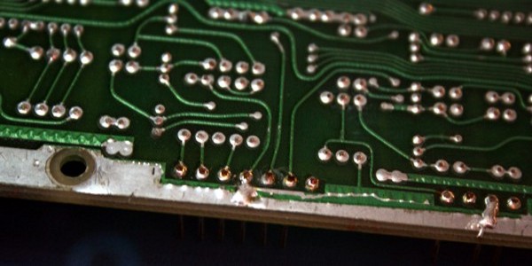
I've also replaced the three radial 100uF 25V caps (bottom right) and cleaned up the solder side of this board with 99% isopropyl alcohol. If you can't get 99%, 91% will work as well. It really cleans up any flux residue from the solder joints. A clean board will also help you spot any cold solder joints or other issues hiding under grime and gunk. One of my favorite tools to do this is an old toothbrush. Pour the alcohol on it and start scrubbing!
Here's a close up of the new connector and the new caps. I only use Nichicon +105C (or better) capacitors when I can. If I can get my hands on military grade caps (they usually are rated at temperatures much higher than 105C) I will use them. Since we know this side of the board runs hotter--based on the discoloration, it's a good idea to use higher rated capacitors if possible. Now I'll need or order some RAM chips, any transistors I don't have, and that axial 22uF 10V capacitor at C1.
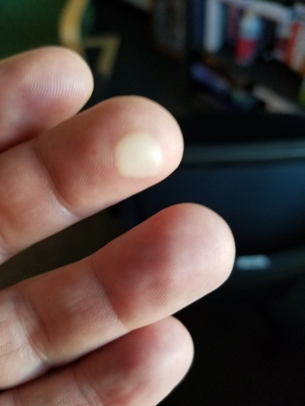
I replaced all the transistors on the board, replaced all the old RAM with new 4116 RAM, replaced the MPU with a new one, replaced the 22uF 10V axial capacitor at C1, and replaced a bad SN74LS04N at 3B and installed a new socket for it. Anytime I replace an IC, I always put a socket in its place if it doesn't have one already. While I was probing the board with a logic probe, I noticed that something was smelling like it was burning. I never saw smoke. So I started touching each chip to see if any of them were too hot. When I got to the 5105 CMOS chip, I noticed it was a little "warm" as you can see from this picture.
That 5101 put a really nice blister on the end of my middle finger. It was red hot. It has since been replaced and now stays super cool.
And a nice new set of 4116 RAM.
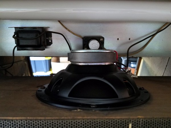
While taking a break from working on the MPU/CPU board (and to let my blister stop throbbing), I decided to replace the speaker since the new set came in and was just sitting on the shelf. I apologize for these pictures as I took them with my cell phone. The lighting is not the best but you get the idea. The old speaker was removed long ago and some crappy 4" speaker (2 Ohm) was hacked into its place. The Defender speaker assembly is not easy to remove. It was a lot easier to put back though after you get to work with it for 10 minutes figuring out how to take it out.
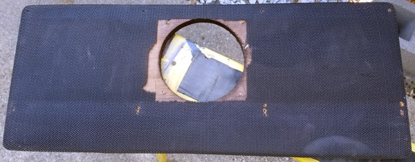
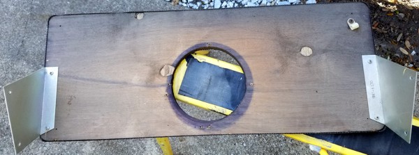
Here's the speaker grill assembly removed. What a complete hack job. I mean seriously, who would do something like this and think it was acceptable?
I removed the old speaker and the make-shift grill and threw that junk in the trash.
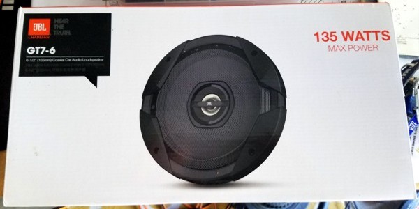
The JBL 6" speakers that I bought are a tad too large to fit this hole. So I took my router and with a rounding-over bit, took about 1/4" out of the back of the hole.
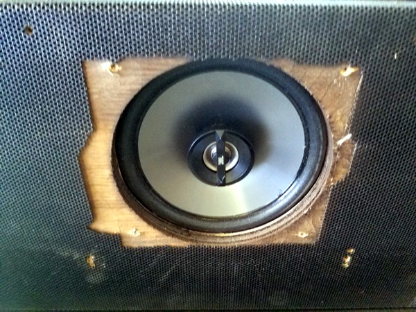
The new speaker sat down over the hole nicely. After aligning it up to center, I put four new screws in and secured it.
Here's a shot of it installed back into place. I'll eventually get around to replacing the old speaker grill with a new one. 100% functionality is my focus at this point.
I chose these 4 Ohm JBL GT7-6 speakers to replace the old ones. Is it overkill? Sure is. But I plan on keeping this game and I want that 8-bit audio to sound nice. : )
I've put this restore on hold until I get ready to redo the entire cabinet.


