D9144 ROM Board
This information applies to the Williams D9144 ROM board. This board was designed to run Robotron and Joust. However, it is capable of also running Stargate (without SC1 or SC2) and Splat! (with two SC2 chips installed). This board can be identified by the serial number 5771-09840-00, which is etched on the PCB. Click on the image below for a high-resolution image of the ROM board.

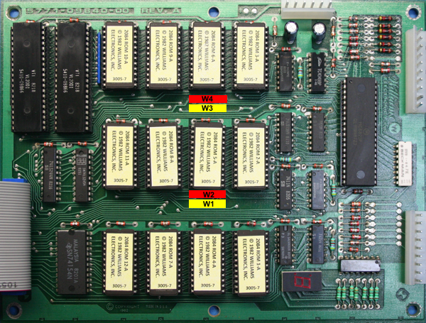
Figure 1 - The D9144 ROM board with jumpers W1 through W4
The D9144 ROM board can be configured to run either 2532s or 2732s EPROMs. A "jumper" is simply a 0 Ohm, 1/4 watt resistor. There are four jumper locations on the D9144 ROM Board. Refer to Figure 1 for the jumper locations. W1 and W3 are highlighted in yellow and W2 and W4 are highlighted in red. In order to run 2532 EPROMs on the board, jumpers W1 and W3 must be installed. In order to run 2732 EPROMs on the board, jumpers W2 and W4 must be installed. These jumpers must be installed in pairs. If you install jumpers W1 and W3, do not install jumpers W2 and W4 (and vice versa).

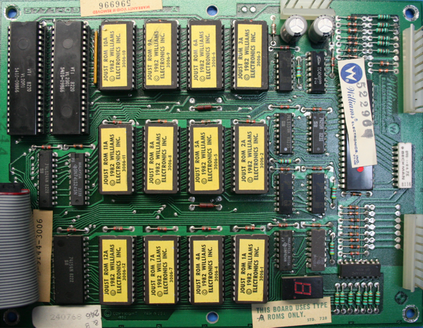
Figure 2 - The D9144 ROM board with jumpers W1 and W3 installed (configured for 2532 EPROMs)

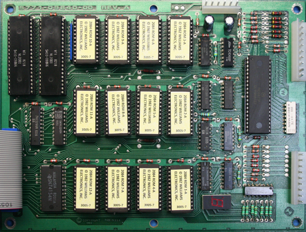
Figure 3 - The D9144 ROM board with jumpers W2 and W4 installed (configured for 2732 EPROMS)
Williams began production of the D9144 ROM board with 2532s installed. However, the supply of these chips dried up so they swtiched over to the 2732 EPROMs. Joust and Robotron ROMs will run on either type of EPROM. The D9144 just has to be configured with the correct jumpers for the applicable EPROM to run correctly.
D9144 ROM Board - General Troubleshooting and Repair
Schematics - The first thing you should probably do before attempting to do any work on a PCB is obtain a legible copy of the schematic. This is the map that tells you how everything is connected together and provides parameters for some of the components. I've been doing arcade repair for many years and what I've learned over that time is that you shouldn't be surprised if you find errors on the schematic or in the manual. The rule of thumb I like to use is "trust, but verify." Use the schematic as a guide but make sure you verify the circuit with reliable tools. Even though the Robotron and Joust run on the same hardware, there are slight variations in the schematic/manuals. I'm just saying, don't be surprised if you find something that is not documented 100% correctly. People make mistakes, even back in 1982. : )
Clean the board - I hate working on a dirty PCB. Before I begin work on any board, I remove all the socketable Integrated Circuits (IC) and set them aside. Next, I prefer to set the board in a stainless steel sink and spray it completely down with Simple Green. With warm water, I use a soft (new) 2" paint brush and lightly scrub the board completely around the each of the components, ensuring to remove all dust, dirt, and grime. Beware, when a PCB has excess flux on it (which many of them do), I've seen the combination of Simple Green and hot water turn the board milky looking after it has been cleaned using this process. When a PCB has a ton of excess flux on it, I like to spray it down with MG Chemicals Flux Remover prior to cleaning. Once all the flux is removed, perform the cleaning process. Once the board is free from dirt, dust, and grime, I'll spray it down with warm water and rinse all the soap off it. Stand the board up and let all the water run off and dab it with a dry paper towel. Next I'll fire up the air compressor (you can use canned air) and blow off any access water from the PCB. You have to let the board COMPLETELY dry before re-inserting any of the ICs or applying power. If you have to let it sit for a couple of days to completely dry, then do so. DO NOT rush this procedure! WARNING: Bad things can happen to you or the components if you apply power to a wet PCB!
Connections - Probably the most common failure of the ROM board is bad connections. The 40-pin IDC ribbon cable at 2J1 is a major culprit in ensuring the board does not function correctly. Intermittent connections through this cable have been the cause of more problems that I've seen. Now, I don't even mess with old ribbon cables. Just replace it from the start and you'll never have to worry about it again. It will save you tons of headaches in the future. In addition, the .156 Molex header pins (and mating connectors) at 2J2, 2J3, and 2J4 become brittle, lose connection, cold solder joints, burn up, etc. Just replace all of these header connectors and you won't have to worry about cold solder joints or bad connections for a long time. Anytime I replace the .156 Molex header connectors, I also replace the mating connectors with Molex KK 3.96mm Crimp Terminal Housings and I prefer to use Molex KK Trifurcon Crimp Terminals.
6821 PIA Chip - The 6821 Peripheral Interface Adapter (PIA) is the integrated circuit that provides the Input/Output interface to the ROM board. I've seen so many of these chips go bad that I hardly even test them anymore. I just replace them with new ones. New 6821 chips are readily available and are cheap enough (under $1 each) to be disposable. You'll find that some ROM boards already have a 40-pin socket installed. If you decide to remove the 6821 PIA chip and your ROM board does not have a 40-pin socket, install one. Over time, the PIA might go out again and you'll kick yourself if you have to desolder the old one and replace it. It's too easy to install a 40-pin socket.
2532 or 2732 EPROMs - Check to see how your ROM board is jumper-configured. Next, ensure you are using the correct EPROMs per the jumpers as detailed above. The next thing to check are the actual ROM chips themselves. It is a good idea to pull each ROM chip individually and inspect each leg. Inspect the socket and make sure none of the legs of the EPROM have broken off into the socket. Also ensure each leg is straight and free from tarnish. If the legs are dirty/tarnished, clean them. If the ROM needs to be replaced, replace it with a new chip and burn the applicable ROM file as necessary. Re-insert the chip ensuring each one is reseated correctly with no bent pins.
SC1 chips - The Special Chip 1 (SC1) "blitter" chips are almost impossible to find. There's not much you can do with these chips when it comes to repair. I normally carefully remove each SC1 chip individually and inspect each leg. If necessary, I'll clean and straighten each leg using the same procedure as described in the ROM section above. Once the chips are cleaned, re-insert them ensuring they are seated correctly into their respective sockets.
7-Segment LED Display - You only need two boards to boot Robotron or Joust; the R8731 CPU board and the D9144 ROM board. When these two boards are powered on, there is a 7-segment LED display located on the ROM board. The LED readout is red. This LED display will tell you if there are any errors during the boot process. If this LED readout reads "0," then there are no errors in the boot process and the game should run as expected. However, if there is a failure during boot-up, a series of numbers will be repeatedly shown on the LED display. The first number is the failure type: 1 = RAM, 2 = ROM, and 3 = CMOS RAM. Refer to the following table for an explaination of boot errors:
| First Digit | Second Digit | Third Digit | |
|---|---|---|---|
| RAM | 1 | Bank # | Chip # |
| ROM | 2 | ROM # | ROM # |
| CMOS RAM | 3 | N/A | N/A |
Table 1 - 7-Segment LED Readout Explained
Voltages - The ROM board runs on +5 VDC. This voltage is applied from the power supply to connector 2J2, pins four and six. With power applied to the ROM board, measure pin 24 at each EPROM to ensure you are getting +5VDC power. If this voltage drops too low, this will trigger the watchdog (reset) circuit on the R8731 board and cause the game to reset. It is very important to maintain a voltage level as close to +5VDC as possible. If the voltage level climbs too high, it could damage the EPROM. Check each voltage for every EPROM. If the voltage is not the proper voltage, trace the circuit back to the power supply (if necessary) until you determine the problem.
Capacitors - There are only two Aluminum Electrolytic Capacitors on the D9144 ROM board. They are C25 (100uF 25V) and C46 (100uF 25V). Don't hesitate, change out both these capacitors even if the ones installed on the board are operational. Chances are the material inside the capacitor is dried up and the capacitor is not longer holding specification. It doesn't make sense to not change out these caps.
Traces - Inspect the board thoroughly. I spend a lot of time after washing a PCB inspecting both sides looking for any damage. Too many times loose boards are thrown in a box with other boards and they bang up against each other--damaging each other's components/traces. Nothing is more frustrating to work on a board for days only to determine one of the traces has been broken due to damage/neglect. Don't rush this step and ensure you check ALL the traces you can. If you suspect something to be damaged, use a DMM in continuity mode and test the trace to ensure it is not broken/damaged.
